Optimizing a 1/10 scale RC body for extreme drag racing requires a deep understanding of fluid dynamics. Consequently, when your vehicle breaches the 100 MPH mark, air ceases to act like an invisible void. Instead, it behaves like a dense, viscous fluid. Managing how this fluid interacts with the microscopic surface of your shell is the absolute difference between a record-breaking pass and a violent blow-over crash. Therefore, we must analyze the exact physical mechanics that govern high-speed runs.
The boundary layer is the thin layer of air molecules directly adjacent to the surface of your vehicle. As your 1/10 scale RC body cuts through the air, the molecules closest to the polycarbonate cling to the surface. This interaction creates a localized zone of high fluid friction. Because of this friction, energy is stripped directly from your motor’s output.
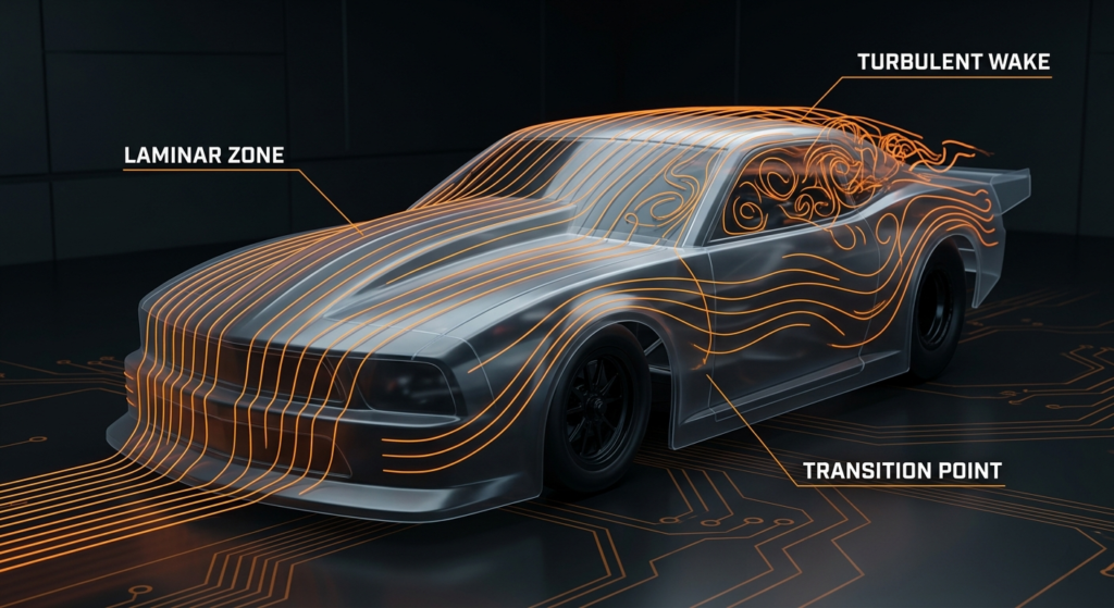
Initially, the air moves smoothly in parallel layers over the front section of the shell. This specific state is known as laminar flow, and it offers the lowest overall aerodynamic resistance. However, as the air travels further down the 1/10 scale RC body, surface friction inevitably disrupts these clean layers. The flow becomes chaotic, which rapidly increases skin-friction drag. Consequently, the transition point where air switches from laminar to turbulent dictates how much total resistance your vehicle experiences during a high-speed run.
When the boundary layer turns turbulent, it thickens significantly. This thickening creates a larger wake profile. Because the wake profile grows, it requires more raw power to push the car forward. Therefore, managing this transition zone is vital for maintaining acceleration throughout the entire length of the track. If you do not control the flow, your top-end speed will plateau prematurely.
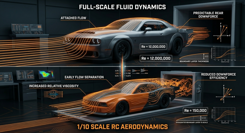
You cannot simply shrink a full-scale dragster design and expect it to work flawlessly. The air molecules themselves do not scale down with your 1/10 scale RC body. Because of this physical reality, smaller vehicles face a much higher relative air viscosity. This phenomenon is governed by the Reynolds number, which drops drastically at smaller scales.
This fluid scaling discrepancy means your 1/10 scale RC body must struggle harder to maintain attached airflow than a full-size car. Air separation occurs much earlier on a smaller chassis. Therefore, specialized RC body shells require exaggerated rear deck overhangs and dropped hoods to force the air to behave predictably at high speeds. Without these modifications, a true-to-scale body will simply lift and flip.
To a small-scale vehicle, air feels thicker, almost like moving through a light fluid or thin syrup. Because the air feels thicker, traditional aerodynamic tricks used on real cars do not translate directly. For instance, tiny muscle car grills that look scale-accurate create massive, destructive high-pressure pockets. Thus, we must redesign the front end completely to handle this structural fluid resistance.
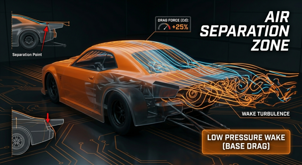
Air separation occurs when the boundary layer loses its kinetic energy and detaches from the surface of your 1/10 scale RC body. This detachment typically happens when the shell curves downward too sharply, such as behind the rear window glass. When the air detaches, it leaves a pocket of low-pressure chaos behind.
When the air detaches, it creates a turbulent low-pressure wake directly behind the vehicle. This pressure drop acts like a physical vacuum, pulling your drag car backward and killing your top-end acceleration. Selecting a 1/10 scale RC body with a gradual fastback design helps delay this separation, keeping the low-pressure zone as small as possible. As a result, the car maintains clean momentum through the traps.
To mitigate this vacuum effect, technical racers often install micro vortex generators. These small ridges are placed just before the separation point on the 1/10 scale RC body. By intentionally creating tiny, controlled pockets of turbulence, they actually re-energize the boundary layer. Consequently, the air sticks to the rear deck longer, reducing the massive base drag that slows down the car.
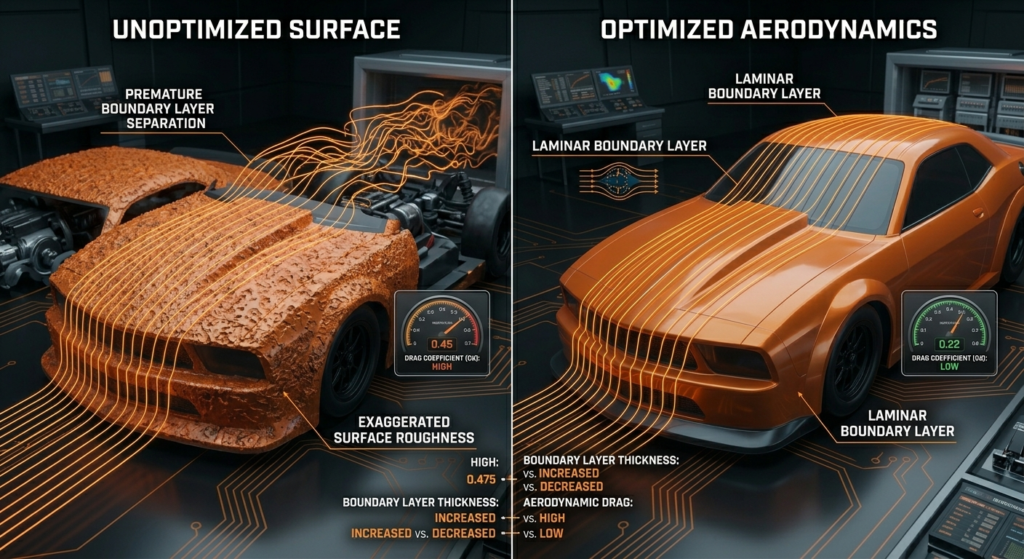
Because boundary layer physics change at high velocities, the surface finish of your 1/10 scale matters immensely. Microscopic imperfections on the polycarbonate can trigger premature air separation, turning smooth air into a chaotic, drag-inducing vortex. Therefore, mechanical preparation of the outer shell is just as critical as your internal chassis tuning.
First, keep the outer surface of your 1/10 scale RC body free of scuffs, debris, and track grime to maximize laminar flow. Second, avoid thick, un-beveled vinyl stickers on the front hood and nose section, as these small ridges can disrupt the delicate boundary layer. Finally, use clear technical tape over body panel seams or windows to prevent high-velocity air from catching an edge and lifting the shell.
Furthermore, we must address the interaction between internal and external air tracking. When air enters through the front wheel wells, it fights the smooth boundary layer moving along the outside of the 1/10 scale RC body. This conflict creates localized pressure spikes that can destabilize the entire front axle. Thus, trimming and venting the shell properly is required to keep both air paths synchronized and efficient.
To truly optimize your setups, you must analyze how air flows over your specific layout. While professional wind tunnels are rare, you can use simple, reliable field testing methods. These diagnostic steps allow you to visualize the exact boundary layer behavior on your chosen design.
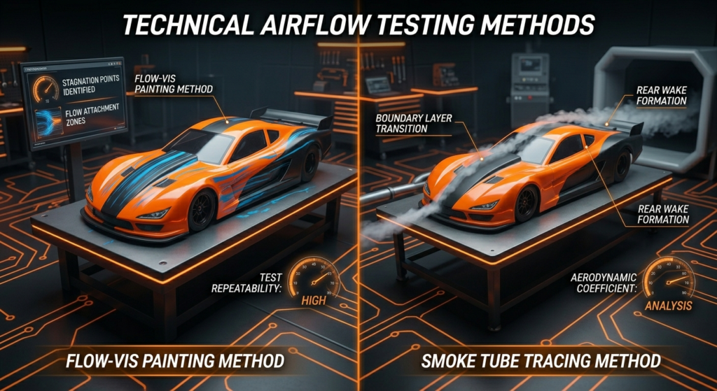
One highly effective method involves mixing a light oil with a fluorescent powder to create a flow-visualization paint. First, apply a incredibly thin layer of this mixture to the hood and sides of your 1/10 scale RC body. Next, execute a full-speed pass on a clean testing surface. The wind will push the oil along the shell, leaving clear streaks that show the exact path of the air molecules.
When you analyze the streaks, look closely for areas where the paint pools or stops moving. Accumulations of paint indicate stagnation zones or early air separation points on the 1/10 scale RC. Conversely, clean, straight streaks verify areas of highly efficient laminar flow. By analyzing these visual markers, you can accurately determine where to add structural reinforcements or relief vents to perfect your aerodynamic package.
© 2026 Supa Media. All rights reserved.
Supa Speed RC